Bidirectional Communication
Serial communication strategies
The physical and digital Boccia ramps have three motors, each motor controls a different range of motion. According to the firmware, the motors name are: elevation, rotation, and drop. The motors control the elevation (or height) of the Boccia ball, the rotation angle of the rails, and the drop mechanism to drop the Boccia ball, respectively.
- The elevation motor uses a linear actuator with a potentiometer to provide feedback. The voltage across the potentiometer can be measured to know the exact position of the motor.
- The rotation and release motors do not have a feedback mechanism to provide precise position. However, they do have optical sensors that are triggered once the motor has reached the end of the desired range of motion. The
rotationmotor has two optical sensors that are triggered when the motor has reached the left or right limits. Thedropmotor has a single optical sensor that is triggered when the motor is moved counter-clockwise (i.e., closed position).
There are three possibilities when having bidirectional communication:
- The ramp is constantly reporting the positions of the motors while being moved.
- The benefit of this is that the physical and digital ramp will behave more similarly and act as true digital twins.
- The drawback of this is that the ramp will have to constantly send information through the Serial port. This can be expensive in execution time and could impact the smoothness of the movement of the motors. More information about the speed of the Serial port communication can be found here.
- The ramp communicates initial position and speed parameters, and Unity calculates the movement time to match that of the real ramp.
- The benefit of this is that there is less demand on the Arduino to constantly send the speed and position values.
- The drawback of this is that the physical and digital ramp might not behave identically since there might be physical factors not accounted in the digital ramp (e.g., additional friction between the ramp materials).
- The third approach would be a hybrid approach. Where the Arduino sends the initial values of the speed and acceleration of the motors, and sends the target position once it has been reached.
- The benefit of doing this approach is that the Arduino will not have to send as many Serial commands as in case 1. Additionally, this could help the Unity program avoid the drawback where the expected position by Unity is not the actual position of the physical ramp.
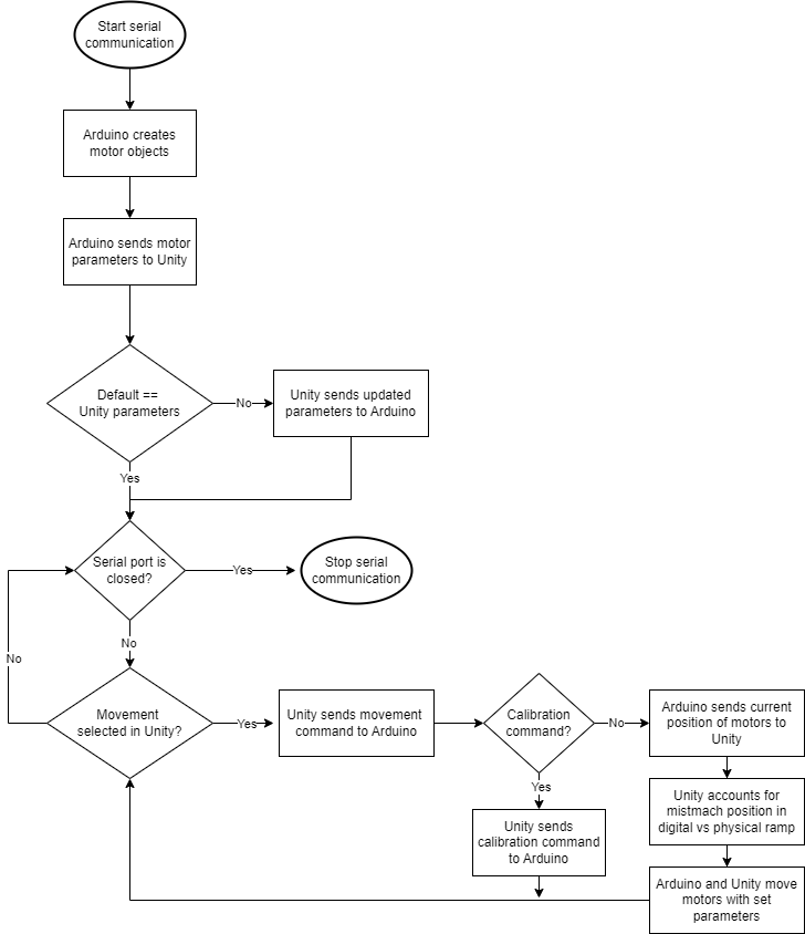
Serial communication flow diagram
Considering that we’ll use the third serial communication strategy, the flowchart for serial communication will be as follows.
Please note the following regarding serial communication:
- The Arduino firmware is reset every time the serial port is opened.
- The default Arduino buffer can only hold 64 characters at a time.
Serial communication rules
To try and reduce the processing needed in the Arduino for Serial communication, we’ll consider the following rules.
- The data transmission of the default parameters can be a multiple descriptive strings with the null character (
\n) at the end. For example, if we want to send the elevation speed, along with rotation speed and acceleration, the resulting string would be something like:
"elevation_speed=255\n"
"rotation_speed=600\n"
"rotation_accel=20\n"
- Movement commands
- The first command that should be sent to the motors should be the calibration commands. These commands start a routine in the motors to find their range of motion (i.e., the voltage across the potentiometer for the elevation motor, and the number of steps for the rotation and release motors). These commands are as follows:
dd: Drop calibration
rc: Rotation calibration
ic: Incline calibration (currently disabled)
ec: Elevation calibration
da-70>rc>ra0>ec>ea50:
Release, rotation, and elevation calibration and move motors to starting position
Target movement commands: These commands instruct the motor the target position to move. This commands should be sent once the user selects an BCI-enabled SPO. The commands sent from Unity to motors is a n-length string where the first character corresponds to the motor in question, the second character to the movement type, and the remaining digits correspond to the target percentage for the elevation motor, or the number of degrees for the rotation and release motors. Individual commands are separated with the > symbol. Note that positive numbers represent clockwise movements, negative numbers represent counter-clockwise movements. The motors are numbered as follows.
# Motor names
d: Drop
r: Rotation
i: Incline (currently disabled)
e: Elevation
# Motor movements
d: Drop ball (special case for drop motor)
a: Absolutme movement (target position)
r: Relative movement (relative to current position)
c: Calibrate
s: Sweep mode
For example, if one wants to move the rotation motor 60 degrees clockwise from its current position, the command to be sent should be rr60.
c. Sweep mode: These commands are sent when the operator presses a key on the keyboard (e.g., WASD for up, down, left, and right). The ramp rotation or elevation will move in the desired position until the keyboard key is released. The commands are as follows:
0: Left/down
1: Right/up
For example, if the letter D is pressed we should move the rotation motor to the right by sending rs1. Once the D key is released, we should send the same command rs1.